A Lempor Exhaust Ejector for the Garratt.
With design information to assist with building your own ejector for a miniature live steam locomotive
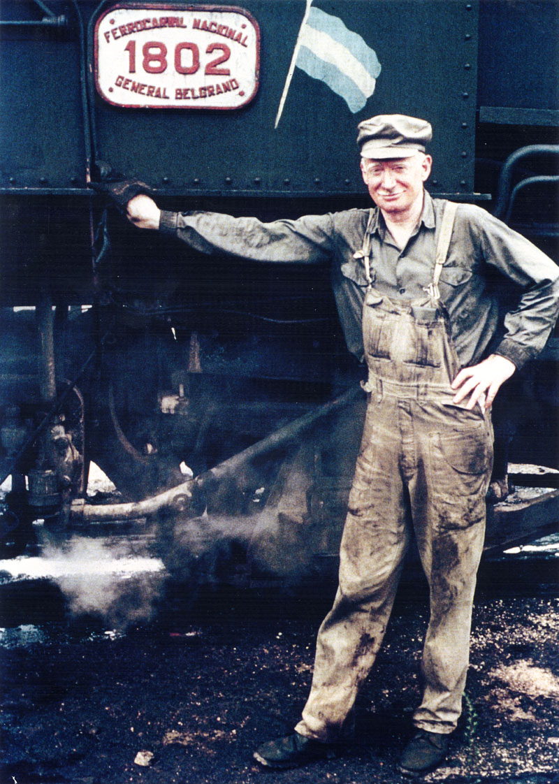
In 1974 Argentinean engineer, Ing. L. D. Porta, wrote the definitive paper on steam locomotive exhaust systems "Theory of the Lempor Ejector as applied to produce draught in steam locomotives". His Lempor ejector is still, thirty years later, considered to be the most efficient way known to draught a steam locomotive. Porta's entire paper and plenty of related information is available on The Ultimate Steam Page. The name "Lempor" comes from his combination of the names "LeMaitre" and "Porta". An excellent descriptive page on the ancestry and development of steam locomotive exhausts is here.
A photo of the man himself taken in 1971 by Richard Campbell, courtesy of Martyn Bane, used here with permission.
During the ten years after Porta published his paper, David Wardale as a steam engineer on the South African Railway worked closely with him to develop the technology on the SAR. The results of this work is covered in detail in Wardale's book "The Red Devil and other tales from the age of steam". This book is required reading for any student of Porta's technology. All the technical information on the ejector design on this page is from "The Red Devil" and the Lempor theory as published on the Ultimate Steam Page, any errors in fact or interpretation here are mine.
After two decades of slow introduction to railways across the globe, Lempor ejectors are just now (in 2005) starting to be adopted by American tourist railways. The Grand Canyon Railway and the Mount Washington Cog Railway are the first to use it in North America. Nigel Day is the engineer in charge of the conversion work in both cases. Read Nigel's comments on the Lempor and draughting locomotives.
Perhaps the best applications reference site for this and other modern steam locomotive developments is Martyn Bane's Steam & Travel Pages where there are numerous photos of Lempor conversions to existing locomotives including a full photo essay of a Lempor exhaust fitted to a South African NGG16 Garratt. Martyn also has pages on related work by David Wardale, Phil Girdlestone, Nigel Day, Shaun McMahon and other steam engineers.
The main attraction of Porta's technology to modern steam locomotive operators is efficiency increases of 30% or more over old-style draughting and combustion methods, saving fuel, money and perhaps not inconsequentially in this day of environmental concerns, reducing smoke emissions. "Porta Technology" encompasses far more than just the Lempor ejector but this page will address the ejector for models only.
Lempor ejectors are beginning to show up on live steam models, a trend I hope this page will assist. A characteristic of model Lempor ejectors seems to be a nearly silent exhaust. Very little "chuff chuff" slogging up a hill with a big train. I am not sure how I feel about that, the chuff seems to be part of the fun of driving a miniature live steam locomotive even if it does waste a little energy!
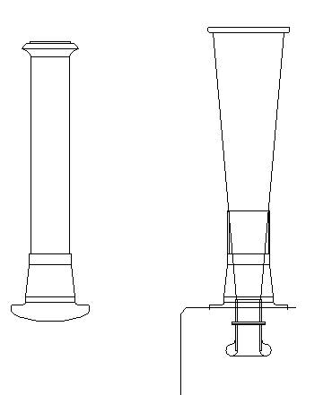
My Old Garratt Stack and a New "Lempor Diffuser".
A same-scale comparison of my original 3" diameter plain stack on the left with the new Lempor diffuser on the right with the mixing chamber below it. The original stack will be cut as shown and the base used as a support for the new diffuser cone.
How the Ejector Works.
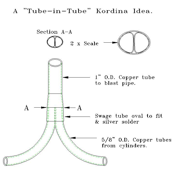
The engine exhaust steam is piped from each cylinder via a manifold to a fitting placed immediately below the blast nozzles. Termed a "Kordina" after the Russian engineer who designed it, it has a central divider to keep separate the two exhaust streams and prevent one cylinders exhaust pulse from increasing the backpressure in the other. The divider ends below a blast pipe, allowing a partial vacuum to be created in the opposite cylinders manifold pipe each time an exhaust pulse of steam goes by from the other cylinder. Each cylinder therefore exhausts into minimal back pressure. The two exhaust streams are combined in the blast pipe, expanded to near atmospheric pressure and directed into the four Lempor exhaust nozzles. The cross-sectional area of the blast pipe should equal that of the exhaust nozzles.
The four nozzles act to split the blast into separate streams to entrain and accelerate smokebox gases within the mixing chamber. They discharge at the point of entry of the mixing chamber bell mouth. Full sized Lempor blast nozzles are of "converging - diverging" section (look up "DeLaval nozzle") and the speed of the steam flow will be near supersonic as it passes through the nozzles. On miniature locomotives the nozzles may have a parallel bore with no detriment to performance (my opinion, if you can prove otherwise please let me know).
At the top of the mixing chamber the choke forms the entry to the diverging cone of the diffuser. The high-speed, low pressure column of steam and gas is converted within the cone into a slower moving higher pressure column as it exits the top of the diffuser. The general principles of this action are the same as that of a boiler-water injector delivery cone. The upward speed of the gas flow from the top of the diffuser is sufficiently slow that smoke lifting "Elephant Ears" are required fittings on many Lempor fitted mainline engines to stop drifting smoke from obscuring the driver's view forward.
The benefit of the ejector is to lower the exhaust steam back-pressure for greater cylinder power output while improving exhaust gas pumping efficiency. You can configure an individual installation to either reduce the back pressure for a given draught or increase the available draught, often both at the same time if the original draughting installation was poor.
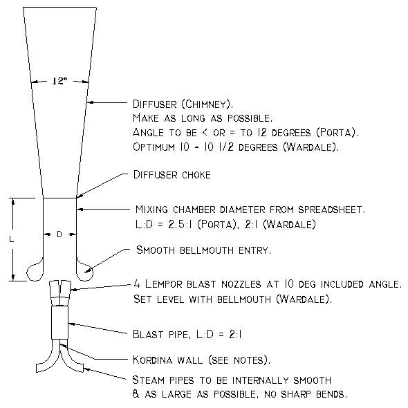
The Lempor Ejector Parts Diagram
The Design Calculations
The calculations as set out by Porta are complex and difficult to complete successfully by someone lacking skill or aptitude for advanced mathematics. Accordingly, I sought help to determine the dimensions needed for my locomotive. Richard Stuart, an Australian engineer and model builder came to my assistance with an excel spreadsheet to crunch the numbers. The spreadsheet supplies two key dimensions, the ejector throat and mixing chamber diameter and the bore size of an individual blast nozzle. All other dimensions can be determined quite easily once these two are known.
Richard has kindly agreed to make this spreadsheet available to the model engineering community. A copy of the worksheet is available here. You will need a copy of Microsoft Excel to open the sheet.
The worksheet is in two parts.
One section calculates the steam gas mass flow rate for your locomotive. The formula used is E. A. Phillipson's equation #61 "Steam Locomotive Design: Data and Formulae" 1936. Note that changes to the operating speed and cut-off used make a significant difference to the results obtained. Pick reasonable maximum settings for your engine. In my case I used 8km/hr and 50% cut-off for a 7-1/4" gauge engine, yours may need to be different.
The other section calculates the ejector nozzle size required for a given mixing chamber diameter and gas mass flow rate. The calculation method used requires that several diameters be tried as required to find the largest individual nozzle size. The correct mixing chamber diameter will be that which yields the largest diameter nozzle, there will be only one correct answer for a given set of input parameters, the worksheet will calculate for two mixing chamber diameters on either side of your pick and graph the results. If the graph is not a well defined convex curve try other diameters until you get a good curve. This takes longer to explain than to do. The correct nozzle diameter for the chosen mixing chamber is the one at the top of the curve and is shown at the bottom of the chart to the right in millimeters to three decimal places.
One other number needed is the level of draught you want through the fire. The default number in the sheet is 735 Pascal (Pa) or about .106 psi. for a large model. You may need to alter this figure depending on the size of your model. As a general rule, the larger the locomotive the larger this number will be. For example, Wardale used 4865 Pa or about .706 psi for his mainline 4-8-4 #3450. My 7-1/4" gauge Romulus locomotive measured 560 Pa on test or .08 psi . The easiest way to make these measurements in the field is with a water manometer. After conversion the Romulus attained 1244 Pa, (127mm or 5 inches of water).
Completing the Design
To complete an ejector design the following dimensions are needed.
The angle of the divergent diffuser cone which is given by Porta as less than or equal to 12°. (In his book "The Red Devil" David Wardale gives this as optimum 10° to 10-1/2°.)
The length of the mixing chamber is given by Wardale as 2 * it's inside diameter. E.g. for my engine 2*38mm = 76mm. (2*1.5 inches = 3 inches).
The blast pipe sectional area should equal the total nozzle area. It's length : diameter ratio is 2:1.
The blast nozzles are set at a diverging angle of 8-10 degrees (see below).
Trial and Error.
Once you have drawn your ejector to suit the particulars of your locomotive and you know the actual areas of the throat and the diffuser top, divide the top by the throat to get the area ratio and compare the result to cell B33 on the lempor calculation sheet. If it is the same, great, if not, input your new number to see if the nozzle size changes. In effect, this process introduces, and compensates for, the length of your particular diffuser. The results of my own Lempor design exercise for my Romulus loco "Lesley" are here.
A Note for Modelers of Standard-gauge Prototypes.
The tall stack diffuser shown above is obviously not applicable to a standard gauge locomotive model. The solution to the problem of not having much headroom above the smokebox for a long diffuser is to set the blast nozzles and bell mouth as low as possible, much lower than usual, in the smokebox. If the proportions are still not sufficient, David Wardale's solution for his locomotives in South Africa was to fit two complete ejectors inline on the centreline. They can also be fitted side by side, transversely. A search for examples of Lempor ejectors fitted to full size locomotives shows that for large express locomotives design engineers have often needed to resort to a double Lempor front end. With careful design a twin installation can also produce lower cylinder back pressure for the same vacuum attained.
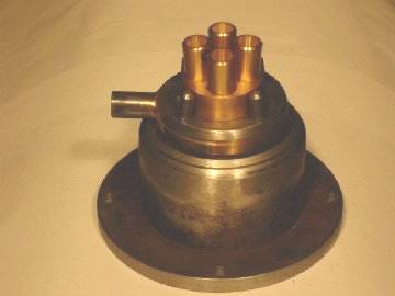
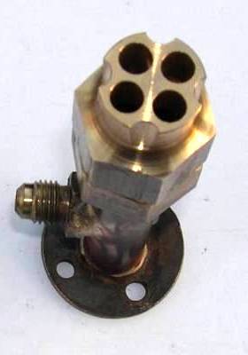
The Lempor Nozzle Assembly.
Four blast nozzles of the correct diameter for the conditions are needed and are set at an 8°-10° diverging angle, as in this photo of the Lempor nozzle and blower assembly made by Richard Stuart for his 7-1/4" gauge Garratt locomotive. A photo essay of this large and interesting locomotive is here.
An alternative way of building the Tuyere or nozzle assembly is to machine a "blast pipe cap" with holes of the appropriate size and angle like this one for Romulus Lesley.
A Kordina for Miniature Locomotives.
This is just an idea at present, I haven't built one yet but it looks as though it might work
To be continued.....
This page copyright Michael Guy 2005.
Forward to the Engine Units page