A Garratt for 7-1/4" Gauge.
The Engine units
This page is, of necessity, incomplete as the engine units exist
only as wheels and frame sides at present (2003). Updates will occur as progress
continues. See ![]() below.
below.
The two Engine units are identical and feature ball bearing axleboxes and equalization between driving axles. The main pivots are adapted from commercially available farm tractor hitch pins and spherical joints from Princess Auto. Steam connections are to be commercial flex hose assemblies.
Frames
The frame plates were water-jet cut from 3/8" hot rolled steel plate by Flow Cut Inc. of Oakville Ontario.
1 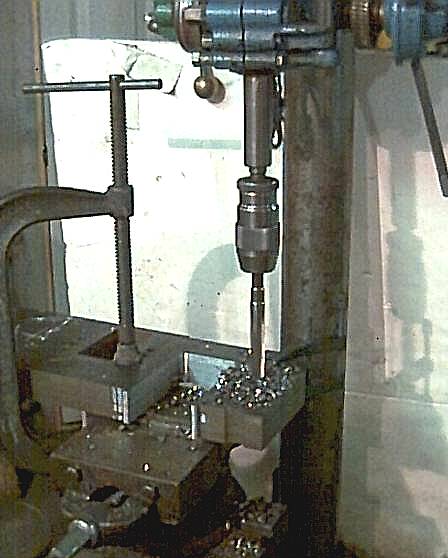 2
2 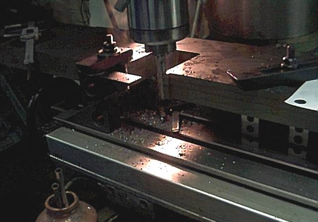 3
3 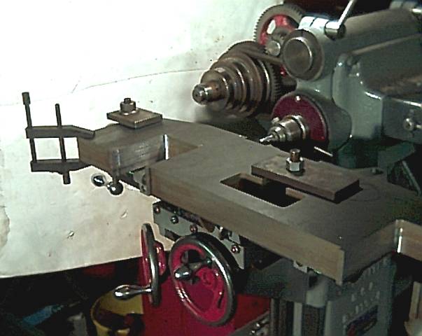 4
4 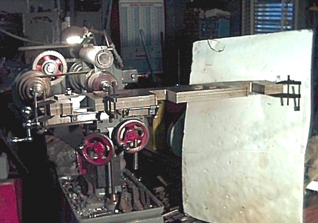 5
5 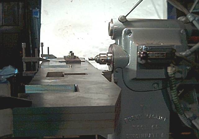
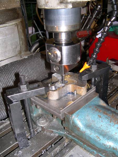
Putting a 5/8" hole through the frames stack. There is a steel block in the vice to which the frames are clamped.
Milling an axlebox slot in the stack of frames on a bigger mill than mine.
Truing a recess for a main crossbeam on the Burke model 'M' milling machine.
I am really pushing the capacity of my little mill here!
All four frames stacked makes the job go a lot faster faster.
I really must get a better camera before going much further with this project!
![]() Ok, camera problem solved.
Ok, camera problem solved.
Frame and suspension detail.
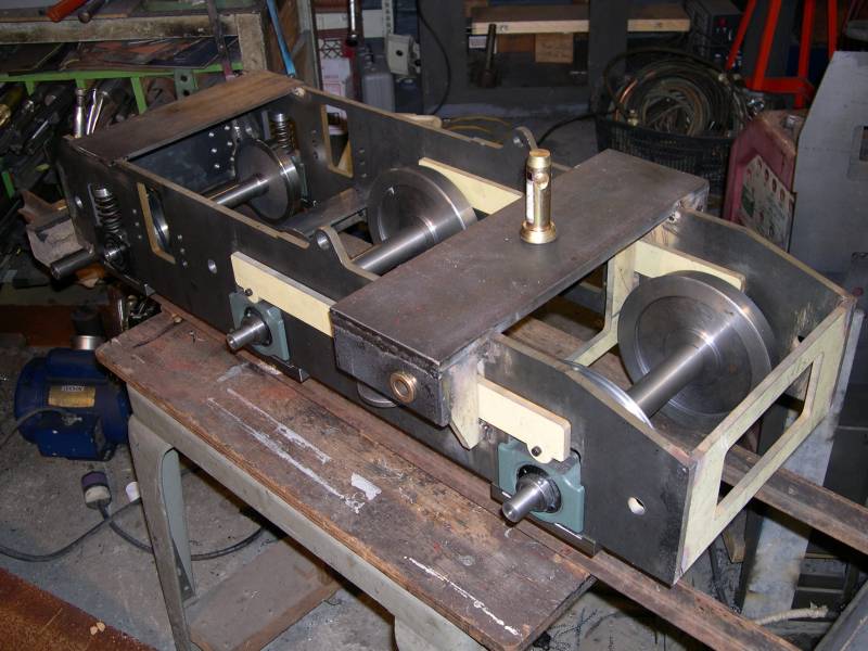
An assembled frame with wheels in place. The yellow beams are equalizers between the driving axles and work in pairs, one each side of a frame plate. The tractor pivot pin is clearly visible.
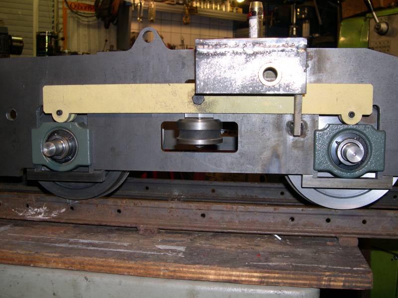
A side view showing the axleboxes, equalizer beams and the central rubber puck "spring". Axle rise and fall relative to the other axle is not restricted, weight on the frame compresses the rubber. The main pivot pin is offset to balance the boiler frame weight with the water tank.
![]() Cranks
Cranks
The Burke mill has now been replaced by a Bridgeport. One of the main cranks is shown being bored for axle and crankpin.
Cylinders
Cylinder castings were supplied to the Romulus design by Reeves 2000 and machined by Alan Butler. An early decision was to 'farm out' some time-consuming sub-assemblies to reduce the total construction time.
Valve Gear![]()
The valve gear was to be Greenly's Corrected gear. This motion features a straight slide and lends itself to robust construction with large pins and bearings. Steam distribution is said to be as good as Joy's gear. At my request Charlie Dockstader added this gear to his animated valve gear program. Thanks Charlie. However, sometime in 2004 I decided that the look of Greenly's gear really didn't suit the locomotive so I changed it to Walshaert's outside admission. Again Charlie's software was invaluable for understanding the gear and designing a version that would suit the engine.
Wheels, Axles & Bearings![]()
The leading wheels were machined from cast iron centres and fitted with tires in stainless steel shrunk in place. Later these were found to be too small in diameter and were re-made from 1014 steel disks. Driving wheels were machined to 7-1/4" gauge 1-1/2" scale standards from 1014 steel disks supplied by Metal Supermarkets.
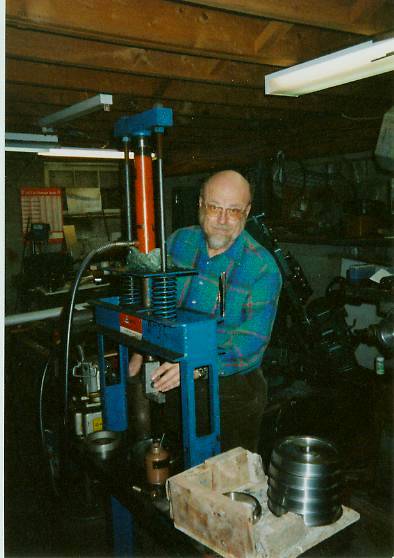
Here is friend Harry broaching key seats in the drivers, a stack of which can be seen to the right. The hydraulic press is power driven making this an easy job.
Leading Axles & Axleboxes![]()
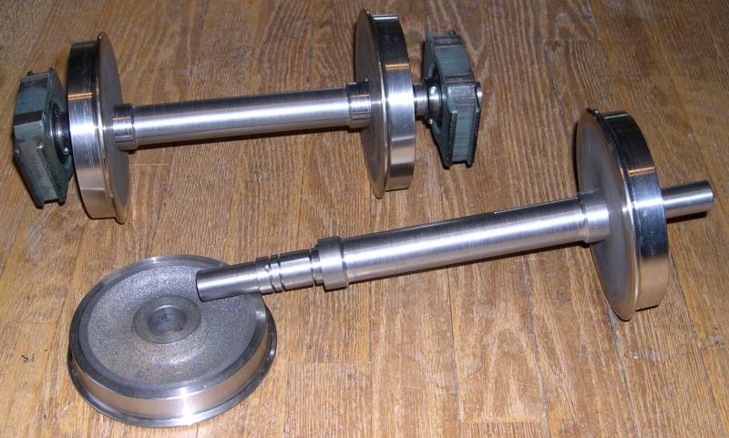
Axleboxes are adapted from commercial NTN "take up" bearings. These are intended to work between a pair of parallel guides and contain a standard self-aligning insert, making a ready made axlebox.
The visible wheel seat shows the snap ring locations and keyway for adjusting the gauge from 7-1/2" to 7-1/4".
Alternator![]()
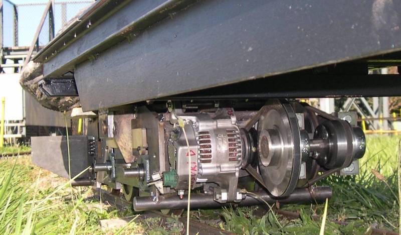
The front engine carries a secret weapon - a belt drive 35 amp 12 volt Suzuki alternator, it will power the headlight, ditch lights and cab illumination for night running. This idea was borrowed (with thanks) from Richard Stuart's Australian Garratt locomotive.
Tanks
The two tanks are for water. The locomotive is coal fired, coal being carried in the left side bunker ahead of the cab. Boiler feed is to be supplied by, injector and a mechanical pump.