A Garratt for 7-1/4" Gauge.
The Boiler
I started first on the boiler as it was a "big lump" and a lot of the locomotive has to fit around it. The size of the boiler was limited by local Government Regulations to 10 square feet of heating surface or less. Using that limit, an arbitrary shell diameter of 12" and the Australian Miniature (steel) Boiler Code as a guide, a short, fat Garratt-style boiler was designed. Construction started in October 2002. The pressure test took place at the end of March 2003. The boiler has 100 square inches of grate area and 9.73 square feet of heating surface.
Some of the following pictures were taken with a "Jam Cam", a really cheap digital camera and are consequently of low resolution. Others are from a single use film camera, scanned to digital and are in consequence not much better than the Jam Cam pix. Click on the thumbnail for a bigger picture.
Using the magnetic drill press to put stay holes through the firebox outer shell.
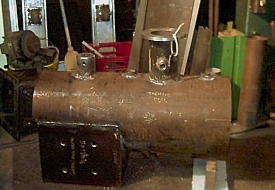
The boiler shell ready for some "innards". The dome, top feed & safety valve bushes, steam turret, outer firebox sides and throat sheet are all welded in place.
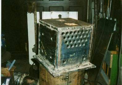
The inner firebox welded up ready to fit to the shell. The foundation ring is of flat plate type and is beveled ready to weld to the outer firebox. Holes for the 3/4" diameter stays and 7/8" flue tubes can be also be seen.
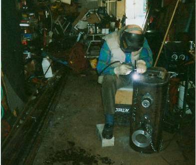
Harry doing the backhead root pass with his TIG welding machine.
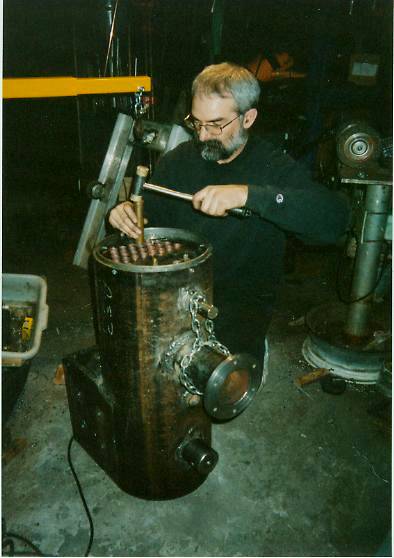
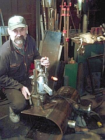
Me using a soft hammer to tap home a copper flue tube. The tubes are 7/8" o.d. expanded into the 1/2" thick steel tube plates.
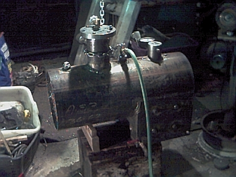
Clearly a short & stubby Garratt boiler. Shown here with garden hose attached and 60 psi of City water pressure applied as a low pressure hydro test to find any leaks. There were three, all incomplete stay welds easily corrected. Non of the other welds or tubes leaked.
I was quite surprised to see the City pressure as high as it was.
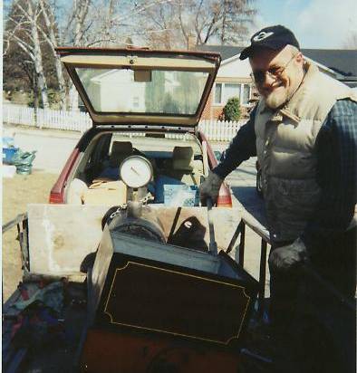
The hydro pressure proof test. Local club boiler inspector Harry is using the Romulus tender hand pump to raise the test pressure to 300 psi, 2-1/2 times the working pressure of 120 psi.
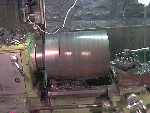
The smokebox going for a facing spin on the 16" lathe. The 12" i.d. tube fit nicely over the chuck body minimizing the overhang.
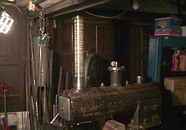
A first fit up of the stack. The smokebox is temporarily bolted in place and the stack assembly is just balanced on top. To make sure it goes on vertical, the roll-in bandsaw table is used as a surface plate and much checking with a level and measuring tape occurred before any bolt holes were drilled. The smokebox door is an aluminum saucepan lid (retired).